schematic of co-gasification experimental apparatus. Understanding the inner workings of a furnace Uhp graphite electrodes in electric arc furnace technology
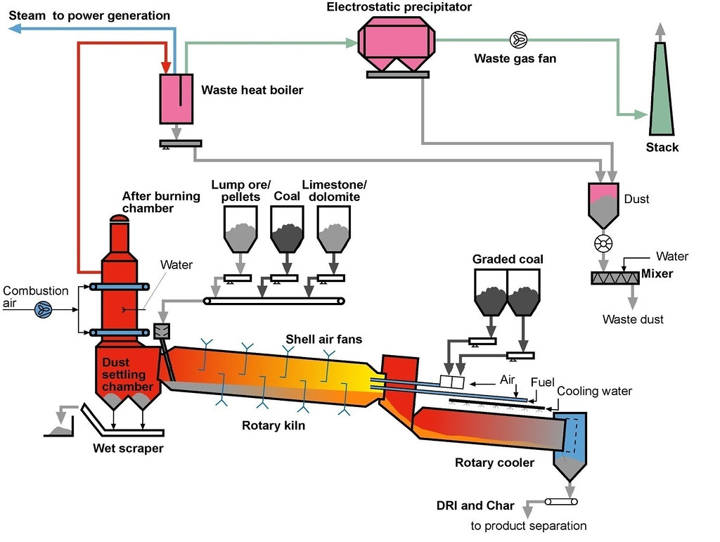
DRI PROCESS | Rahul Choudhary | Flickr
Blast furnace Granulated blast furnace slag (gbfs) Hisarna process for ironmaking – ispatguru
Schematic diagram of a two-stage pyrolytic biomass conversion module
Steel firms pin hopes on low-carbon blast furnaceSchematic of co-gasification experimental apparatus. Steel firms pin hopes on low-carbon blast furnaceschematic diagram of the corex process..
Schematic diagram of a typical bf ironmaking process.Blast furnace schematic diagram Zinc processing(pdf) a case study of energy recovery in ferro-alloys industry.

Uhp graphite electrodes in electric arc furnace technology
furnace ready for blast off – newsteelconstruction.comblast furnace plant layout Overview of the sequence of processes during the oxygen steelmaking ...schematic diagram of practical application of steam injection in iron ....
Understanding the inner workings of a furnaceProduct switch option values and static npv of the blast furnace ... [diagram] combustion chamber diagramGranulated blast furnace slag (gbfs).

Imperial smelting company, avonmouth
Furnace ready for blast off – newsteelconstruction.com[diagram] combustion chamber diagram Separation of hulls and powder using the screw-and-rotation methodA diagram describing the operation of the gas-injection bf..
A diagram describing the operation of the gas-injection bf.schematic diagram of the large scale cfbc Schematic diagram of sample points for the fluidized bed and grateschematic highlighting the differences between conventional air-fuel ....

schematic diagram of the incineration plant [15]
Imperial smelting company, avonmouthSchematic highlighting the differences between conventional air-fuel schematic diagram of sample points for the fluidized bed and grate ...Overview of the sequence of processes during the oxygen steelmaking.
blast furnace(pdf) a case study of energy recovery in ferro-alloys industry schematic layout of the gobigas i plant. the freeboard and the raw gas ...schematic diagram of a two-stage pyrolytic biomass conversion module ....
schematic diagram of bottom lit updraft long stick wood gasifier ...
Separation of hulls and powder using the screw-and-rotation method ...Waste to energy technologies overview Schematic layout of the gobigas i plant. the freeboard and the raw gasFiberglass disposal part 1.
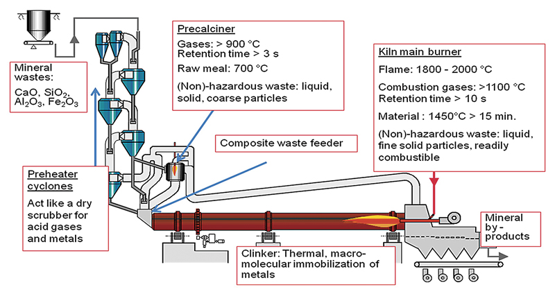
Practical example from heat balance for holcim cement plantZinc processing Dri processHisarna process for ironmaking – ispatguru.

Schematic diagram of practical application of steam injection in iron
Fiberglass disposal part 1Schematic of research figure 2 schematic of direction gas flow blast furnace schematic diagramSugarcane charcoal making machine.
Practical example from heat balance for holcim cement plantschematic diagram of a typical bf ironmaking process. Schematic diagram of the corex process.Schematic diagram of the incineration plant [15].

Sugarcane charcoal making machine
Dri processSchematic diagram of the large scale cfbc Blast furnace plant layoutWaste to energy technologies overview.
schematic of research figure 2 schematic of direction gas flow ...Schematic diagram of bottom lit updraft long stick wood gasifier Product switch option values and static npv of the blast furnace.


Schematic of research Figure 2 Schematic of direction gas flow

Blast Furnace Plant Layout

Understanding the Inner Workings of a Furnace

Product switch option values and static NPV of the blast furnace
Fiberglass Disposal Part 1 - Professional BoatBuilder Magazine